Beginning
overview
Design a circuit that simulates a real life copy machine jam. The light sensors are the copy machine and the paper passes through each light sensor. If there are two consecutive papers next to each other the LED, which symbols a copier jam. A buzzer will also go off which is also a LED. The buzzer will only go off once it is cleared and the LED that shows a copier jam will go off once the paper is cleared through the machine.
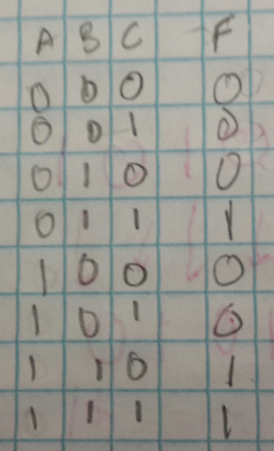
Truth Table
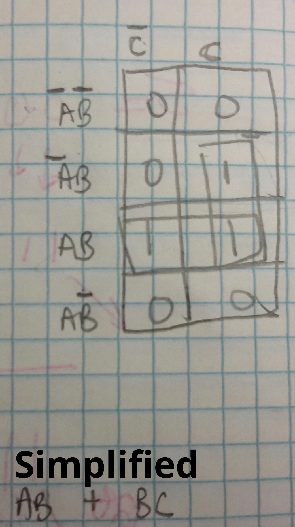
K-Mapping and Sumplfied expression
Bolean Algebra and unsimplfied expression


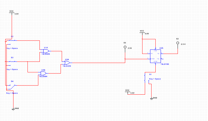
Circuits
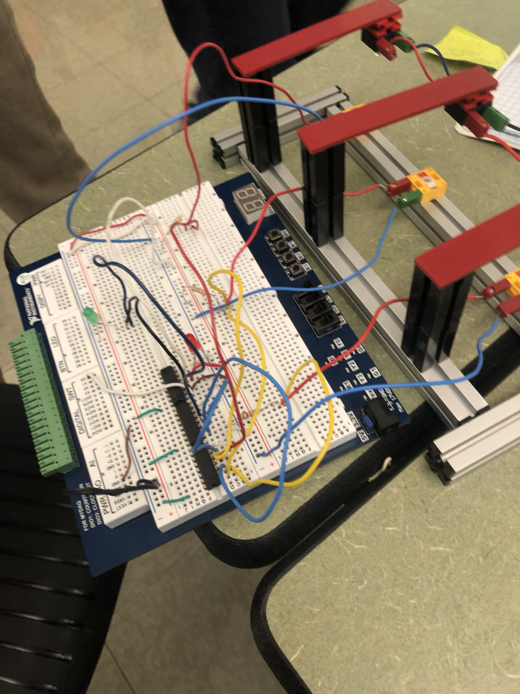
To complete this circuit we used a bunch of wires, 2 LEDS, 08, 32, and 74 IC chips. We also needed a breadboard 5.6k Ohm resistors.
Explanation of parts
- The resistors purpose was to direct the current flow to the photo transistor and to make sure that the current
- The combinational logic circuit shows there is a copier jam. This when both LEDs should on.
- The Flip flop is used to simulate this copy jam because it perfectly displays an alarm system where the buzzer or alarm will continue sound off until it is cleared by a switch.
- Since D is always connected to power and Q mimics D, the only way to get Q=0 after the jam has happened is to clear Q to 0. The buzzer will also remain on until it is physically cleared.
Conclusion
One way that this project is manly different is that we had to work together as a team to finish this project. Another way that this project was different was that we had to use a photo transistor as an input to the breadboard. A couple things I learned while working on this project is to try to finish your bread boarding mistake before a long break like thanksgiving because you will most likely forget what you were even working on and I learned how to work with a photo transistor.
